


Magnetic coupling is one of the important downstream applications of permanent magnetic materials. Today, we will systematically introduce the principle, classification, and application of magnetic coupling, and also talk about the permanent magnet in magnetic coupling.
What is magnetic coupling?
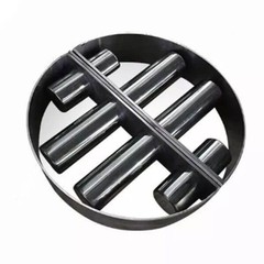
Coupling is an important component in mechanical transmission, which transmits torque by connecting the driving shaft and the driven shaft. The following figure shows several common coupling forms, which can help you better understand what coupling is.
|
|
|


Traditional couplings are contact-type and have relatively complex structures. They will wear out during daily operations. If overload occurs, other mechanical parts will be seriously worn out, which is very unfavorable to the stability of mechanical operation equipment. If the driving shaft and driven shaft of the coupling need to work in two different media isolated from each other, sealing elements must be used for dynamic sealing. In this way, there is a problem of either increasing the rotational resistance to ensure reliable sealing or leaking due to poor sealing. In addition, as the sealing elements wear and age, leakage will be aggravated, especially in systems with harmful gases (harmful liquids). Once leaked, it will pollute the environment and endanger life.
Magnetic couplings are non-contact couplings, generally composed of two magnets, with an isolation cover in the middle to separate the two magnets. The inner magnet is connected to the transmission part, and the outer magnet is effectively connected to the power part, transmitting power through the interaction of magnetic field NS pole coupling. Magnetic couplings have the function of buffering and vibration absorption of elastic couplings. In addition, it breaks the structural form of traditional couplings and adopts a new magnetic coupling principle to achieve force and torque transmission between the driving shaft and the driven shaft without direct contact, and can transform dynamic seals into static seals to achieve zero leakage. Therefore, it is widely used on occasions with special requirements for leakage.

Classification of magnetic couplings
Common magnetic transmissions include synchronous transmission, hysteresis transmission, and eddy current transmission. Due to their respective characteristics, they are used in different fields. Synchronous transmission refers to the synchronization of output and input. There are two common synchronous coupling structures: planar magnetic coupling and coaxial magnetic coupling.
1. Planar magnetic coupling
Structure: Magnets are installed on two discs of the same diameter in a manner of crossing NS poles. When in use, the two discs are installed on the driving shaft and the driven shaft respectively, leaving a certain air gap in between.
Principle: Since the N pole of magnet A attracts the S pole of magnet B on the opposite side and repels the N poles on both sides of magnet B, it is ensured that within a certain torque range, the driven shaft and the driving shaft keep rotating synchronously.

Torque: This planar transmission has a simple structure and does not require high coaxiality of the two shafts during installation. Since it uses the principle of plane attraction, the smaller the air gap, the greater the torque. In addition, since the torque transmitted is proportional to the disc area, the torque of this magnetic coupling cannot be too large, otherwise it will be too large and difficult to install.
2. Coaxial magnetic coupling
Coaxial magnetic coupling is the most widely used synchronous transmission device at present, and its typical application is the magnetic pump.
Structure: Coaxial magnetic coupling consists of the outer rotor, inner rotor, isolation sleeve, and bearing system. Magnets are installed on the outer circumference of the inner rotor and the inner circumference of the outer rotor. The magnets are even poles and arranged circumferentially in NS cross mode. Align the working surfaces of the magnets of inner and outer rotors, that is, automatic coupling. The isolation sleeve and bearing system are mainly used in the structure of the magnetic transmission seal.
Air gap and isolation: There is a certain air gap between inner and outer rotors, which is used to isolate active and driven components. The air gap is mostly between 2mm-8mm. The smaller the air gap, the higher the effective utilization rate of the magnet, but the more difficult the isolation; the larger the air gap, the more convenient the isolation, but the less effective the utilization of the magnetic field of the magnet. The radius position of the air gap is the working radius of this magnetic coupling. When designing, the torque of the required transmission can be obtained by adjusting the size of the air gap radius.

When the load exceeds the maximum torque, the transmission begins to "slip", that is, the magnets jump from the current coupling state to the next coupling state by circular displacement. During this slipping process, the magnetic field in the air gap changes rapidly, and the magnets of the inner and outer rotors are demagnetized by each other at the same time, generating heat. In a short period, the temperature can quickly rise to more than 100 degrees Celsius, causing the magnets to demagnetize and the transmission to be scrapped. Therefore, although this type of transmission can play the role of overload protection, it is generally not used as an overload protection device.
3. Hysteresis Transmission

Hysteresis transmission is a transmission method that applies the hysteresis principle. Common hysteresis transmissions are generally coaxial structures similar to synchronous transmissions. The difference is that the inner and outer rotors use different magnetic materials. Generally speaking, the inner rotor (active shaft) uses materials with high coercivity and high remanence, such as neodymium iron boron. The outer rotor (driven shaft) uses magnetic materials with low coercivity, such as aluminum nickel cobalt. The magnets on the active shaft are arranged crosswise according to the NS poles. When the load is not greater than the rated torque, the driven shaft rotates synchronously with the active shaft; when the load exceeds the rated value, the inner and outer rotors slip, and only the rated torque is transmitted to the driven shaft. The excess energy is released in the form of heat during the process of the inner magnet charging and demagnetizing the outer magnet.
This hysteresis transmission structure is commonly found in magnetic capping machines, which can ensure that the bottle caps have sufficient tightening force without damaging the bottle caps.
4. Eddy Current Drive

Replacing the permanent magnet material of the driven part of any of the above-mentioned magnetic couplings with non-ferromagnetic materials with good conductivity, such as copper and aluminum, can achieve eddy current transmission, although the transmission efficiency may not be very high. The simple disc eddy current transmission structure is shown in the figure:
On the active disc, high-performance magnets are installed in the NS cross mode. The driven disc is made of copper with good conductivity. The magnetic lines of force pass through the copper disc. The active disc rotates, and the eddy current drives the driven copper disc to follow the rotation.
Eddy current transmission can be synchronous or asynchronous. To be precise, synchronous eddy current transmission generally has a small amount (5%) of asynchrony. For example, the input is 1000rpm and the output is 950rpm. This asynchrony can be accepted as transmission loss. The typical application of asynchronous eddy current transmission is the tension control system of the retractable line. Through special control, the speed regulation function within a certain range can also be achieved through eddy current transmission.
Permanent magnets used in magnetic couplings
The invention and development of magnetic couplings are closely related to the continuous progress of permanent magnetic materials. Magnetic couplings were originally made of ferrite materials, but due to their low magnetic properties, they can only transmit smaller torques in the same volume as traditional couplings, which limits the development of magnetic couplings.
The magnetic properties of the second-generation permanent magnetic materials samarium cobalt and aluminum nickel cobalt magnets (AlNiCo) are much higher than those of ferrite materials, so the manufactured magnetic couplings can transmit larger torques. However, the high prices of samarium cobalt and aluminum nickel cobalt seriously restrict the development of magnetic transmission couplings.
The maximum magnetic energy product (BH) of neodymium iron boron (NdFeB) permanent magnetic material is 428kJ/m3, making it the third generation of permanent magnetic material after samarium cobalt. NdFeB not only has better magnetic properties but also has stronger market competitiveness. NdFeB has a high magnetic energy product, requires less, has good processing performance, can be cut and drilled, and has a high yield rate. Therefore, it can reduce the volume of magnetic couplings, reduce costs, and improve efficiency. It has been widely used in magnetic transmission couplings.